
Digital Audio Demystified
TOC
Sample Rate Demystified
Fast Facts & Definitions:
The Nyquist-Shannon Theorem: To capture a sound frequency accurately, your sample rate must be at least double the highest frequency you want to record:
Nyquist frequency = Maximum Frequency Captured
Sample Rate = 2 x Nyquist frequency
Industry Consensus:
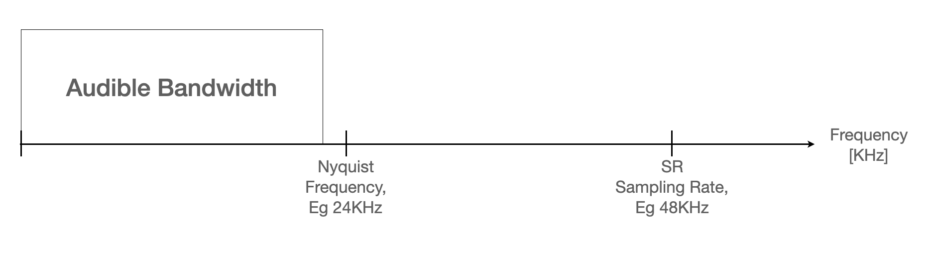
- Thanks to the work of Shannon and Nyquist, we understand that the sample rate determines the frequency bandwidth of the recorded signal - particularly the upper frequency limit, known as the Nyquist frequency. The math is simple: the Nyquist frequency is half the sample rate. For example, with a sample rate of 48kHz, signal frequencies up to 24kHz are recorded.
- Doubling the sample rate also doubles the file size for a given bit depth and recording time.
- Certain industries have their preferred sample rates (such as 48KHz in broadcast and video streaming), and it's advisable to adhere to those standards.
- Unnecessary sample rate conversions should be avoided.
- To my knowledge, the world-population of consumers who demanded a refund because a sound was recorded at the wrong sampling rate is: ZERO. Correct me if I’m wrong.
Areas of Disagreement:
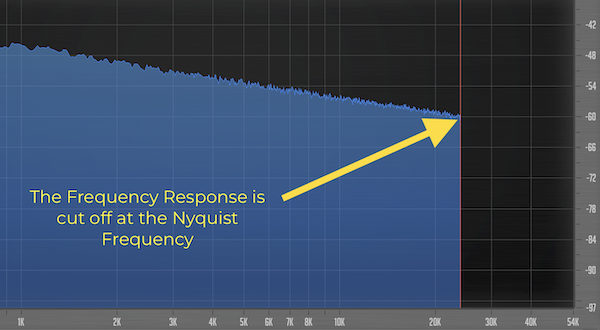
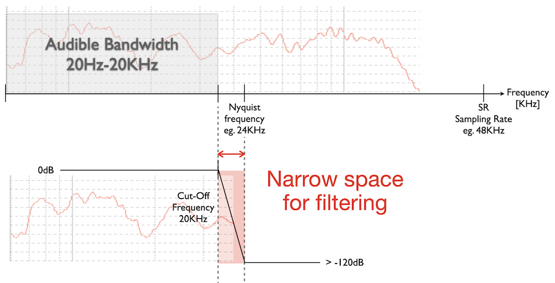
Imagine the sample rate as an extremely steep high-cut filter across every thing in your production.
Similarly, engineers who utilise their digital audio workstations only as tape machines may have different perspectives than those heavily reliant on virtual instruments and digital plug-in processing.
In short: the industry doesn’t agree on the best sample rate.
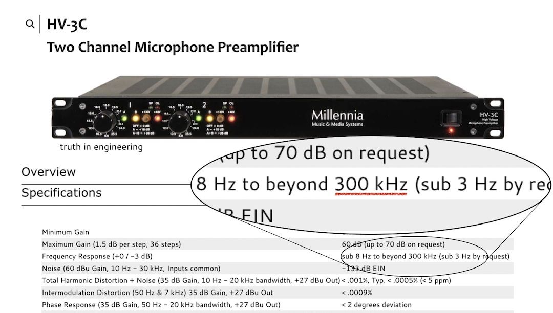
To illustrate this, let's draw a parallel from the world of analogue audio.
So, does high end sound require a wide bandwidth extending into the ultra-sonic range? Or is a wide bandwidth a by-product of high-end audio design and the desire for a superior transient response?
It's a bit of a chicken and egg scenario - both affect one another.
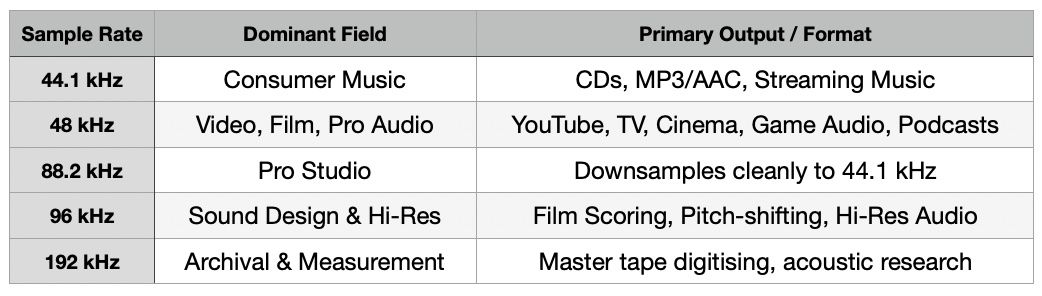
My Sample Rate Recommendations - Short and Punchy:
Coming soon:
The next chapter on Bit Depth, word length and the numbers 16, 24 and 32.
Leave your email below to get notified.
Bit Depth Demystified
Fast Facts & Definitions:
Industry Consensus:
In a linear PCM system, each bit represents approximately 6 dBs of dynamic range. (fellow nerds, you may enjoy the equation in the side-box for exact figures).
S/E = 6.02 * n + 1.76dB
n = 12 bit ➔ 74dB
n = 16 bit ➔ 98dB
n = 24 bit ➔ 146dB
In the analogue domain, the upper limit of the dynamic range is restricted by distortion, which can manifest abruptly (e.g., transistor technology) or more gradually (e.g., transformer or tube technology). Distortion of around 0.5% total harmonic distortion (THD) typically quantifies the upper limit of the dynamic range.
On the bottom end of the scale, the dynamic range is limited by the noise floor of a device.
In the digital domain, the top of the dynamic range is the clipping point, at which the binary number range has reached maximum.
AD-converter clipping is known to be unpleasant to the ear and it is good practice to avoid it, although I’ve seen it done for creative reasons.
At the bottom of the scale, we encounter quantisation error, which you can envision as the digital equivalent to analog self-noise.
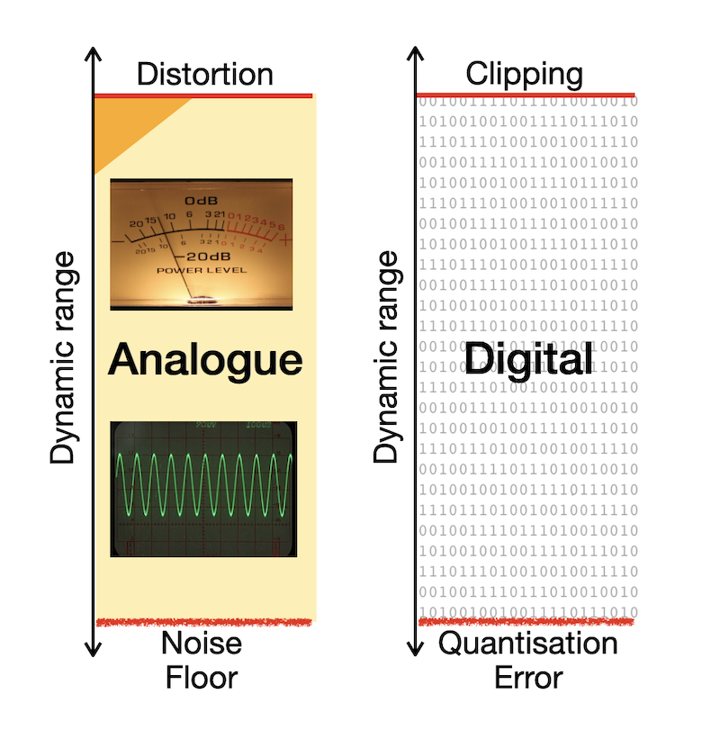
The actual dynamic range should be stated in your converter’s operating manual, and it is always less. Many quality ADCs have a practical dynamic range of 120dB to 128dB and it is my understanding that the analogue components inside the converter (such as line input stages, resistors or balanced line drivers) are the “bottle-neck” here. Either way, modern converters match or exceed the human hearing range, therefore we don’t have to worry about quantisation error degrading our signal, if one gain-stages with care.
16bit or 24bit?
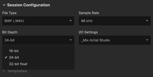
It's worth noting that 32-bit converters have also made their way into studio devices like AVID's Carbon interface, although the absence of "float" in the name suggests it may be a linear PCM converter.
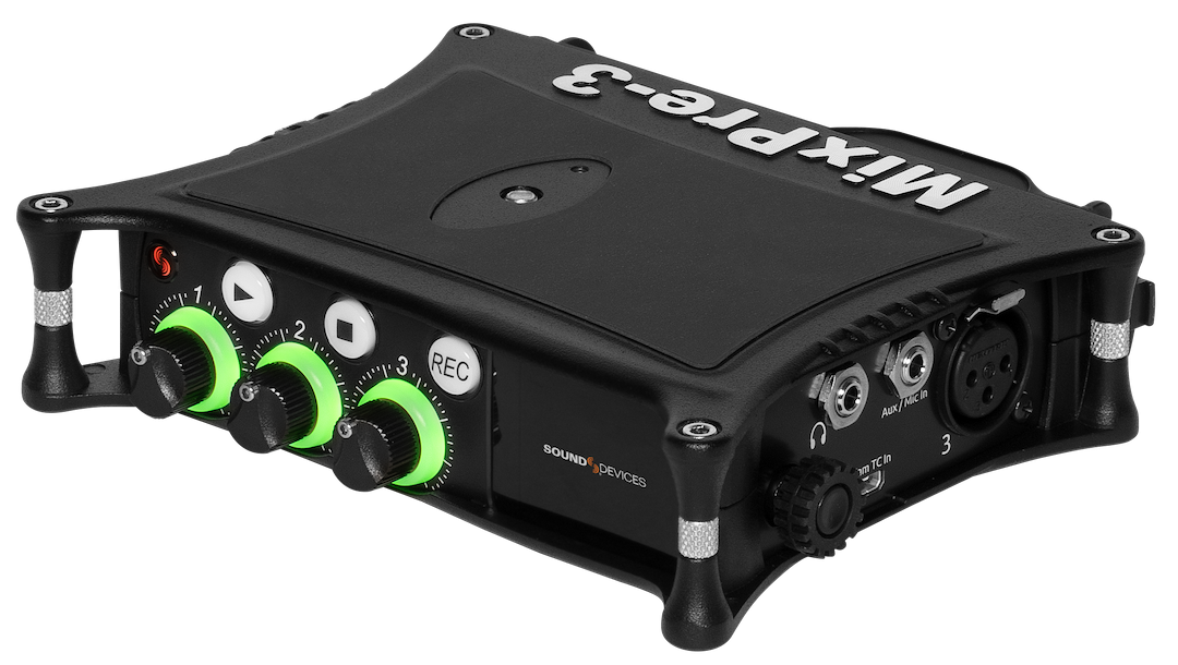
The acclaimed Sound Devices MixPre-3 32-bit-float recorder
Areas of Disagreement:
From 2 to 16 Million: Debunking Volume Steps Misconception
While this is adequate for the number range from 0 to 1, to express the decimal number 2 in a binary system, a second bit is required. So, the decimal number 2 equals the binary number 10 (pronounced ‘one zero’ to avoid confusion).
I’m sure you get the silly joke in the title now :-)
-
Decimal
-
Binary
-
0
-
00
-
1
-
01
-
2
-
10
-
3
-
11
possible combinations = 2n,
-
word length
-
resolution steps
-
8 bits
-
256
-
12 bits
-
4,096
-
16 bits
-
65,536
-
24 bits
-
16,777,216
Double Trouble! 32 vs. 64: The Battle of the Bits
-
Bit Depth
-
Bit Rate
-
The quantity of bits used to measure the amplitude, typically 16-bit, 24-bit or 32-bit float.
-
The amount of data transmitted per second, typically measured in kilobits per second (kbps)
Myth: busted!
32-bit float already provides a noise floor so low it could accurately measure the diameter of a proton. 64-bit float summing simply prevents mathematical rounding errors when stack-loads of tracks (several hundreds), heavy automation, and endless plugins are summed together. It’s about mathematical precision during complex calculations, not an audible 'audio quality' upgrade.
My Bit Depth recommendations, short and punchy:
Coming soon:
The next chapter on Master Faders workflows, myths & analogue / digital facts.
Leave your email below to get notified.
Join the Inner Circle
Master Faders Demystified
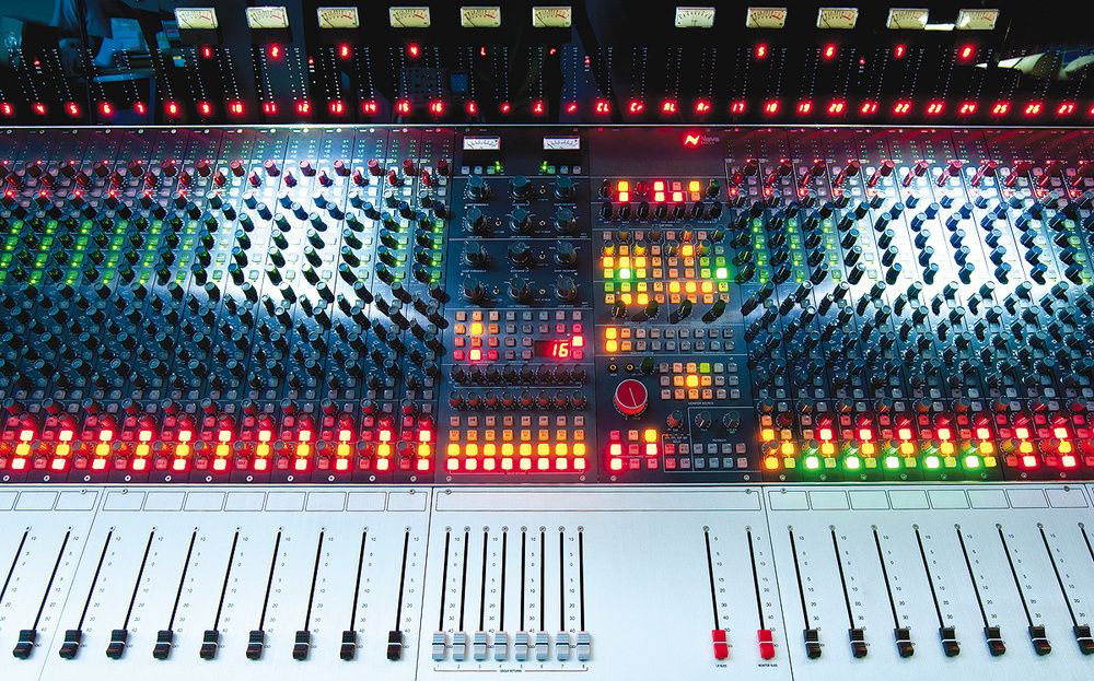
Analogue mixes have the best signal-to-noise ratio with the master fader at 0dB. [Customseries 75 console, powered by Neve]
Next, summing stages began working with a few more bits internally, allowing adjustments on the master fader instead of multiple channel faders. This approach preserved the mix balance but impacted the sum's resolution due to accumulating rounding errors and poor (or total lack of) dithering. Back then, I want to say in the 90s, leaving the digital master fader at unity gain actually resulted in better sound.
Once more, music creators grumbled, and technology companies pushed technology ahead.
Let’s jump forward to the mid-late nineties when Digidesign’s TDM mixer took over the world of professional audio, which it dominated for almost 20 years. It utilised 48bit linear summing (+8 bit overflow). That’s when I first witnessed a demonstration in which the “master faders sound bad” myth was officially busted without any reasonable doubt.
Since then, we've witnessed the evolution to 64-bit-float summing with the introduction of HDX for big studios with the budget in 2011, and Pro Tools 11 for everyone else in 2013. Similar summing technology is found in most DAWs today. Null-tests have repeatedly demonstrated that the master fader has no negative impact on the sound, not even a single bit (pun intended!).
Deliberate attempts were made to overload the summing bus (a near-impossibility in 64-bit-float summing). To compensate, the master fader was set to an extremely low level, yet it did not affect the mix resolution. The output perfectly nulls against the source.
Old cobwebs cleared, myth busted - fair and square. While Pro Tools 11+ and some DAWs use 64-bit float summing, others use 32-bit float summing. For the master fader, it doesn't matter: even a 32-bit float summing engine has over 750dB of dynamic range and handles above-zero signals flawlessly. Whether your DAW sums at 32-bit or 64-bit float, the master fader acts as a transparent volume control. The output perfectly nulls against the source.
My master fader recommendations, short and punchy:
Coming soon:
The next chapter on Recording Levels will be published soon.
Leave your email below to get notified.
Digital Recording Levels Demystified
Personally, I find the word “Always” in the statement problematic. Today, this workflow is more of a personal choice, rather than a requirement - and blindly following this workflow can have negative side-effects in certain situations.
This practice originated in the mid-80s, in the early days of digital recorders. Those devices were jittery and poorly dithered by today’s standards (if dithered at all). With these grainy-sounding 12-bit or 16-bit converters, preserving every bit of resolution was paramount.
Fast forward some 30 years, and today’s converters don’t suffer from the same troubles anymore. The technology has long gone through its teething stages, and early hiccups have been addressed. All modern converters I've had the pleasure of working with deliver the same clean and transparent results at all reasonable recording levels - hot, and also a little cooler.
Studio Operating Levels
-
0VU
-
= 1.228V(RMS) =
-
+4dBU
In 1942, the Acoustical Society of America officially defined the Studio Operating Level standard we still use today
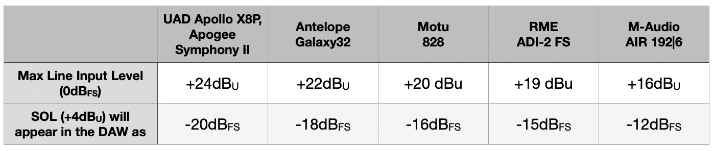
ADC max line level input specifications in comparison
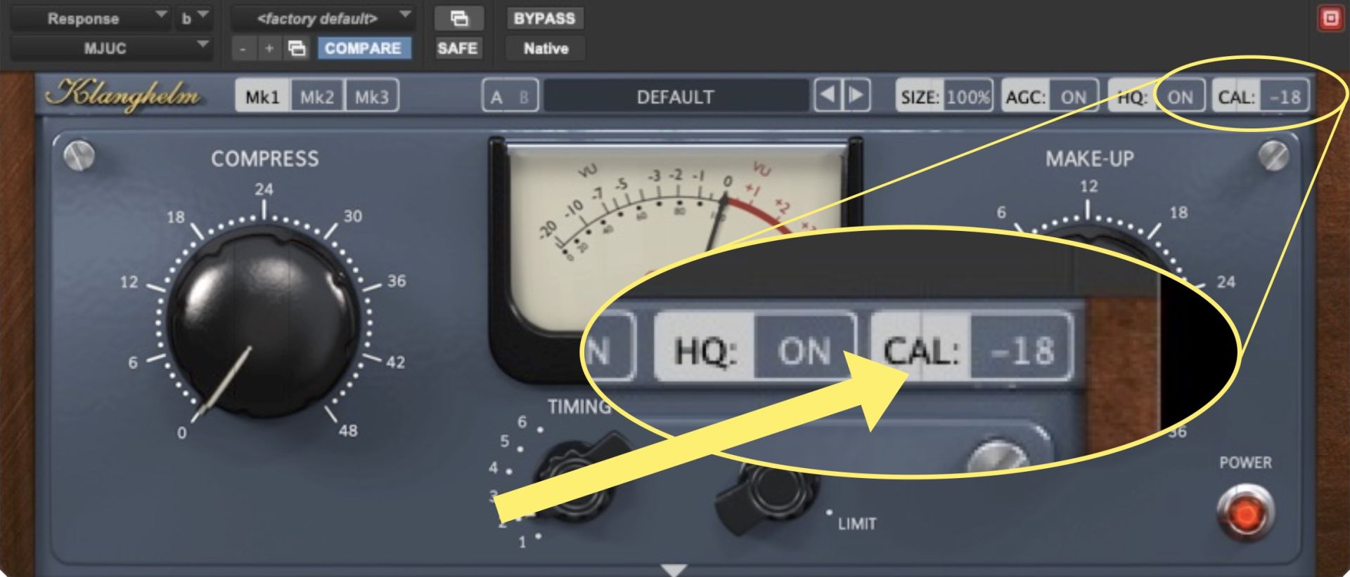
Klanghelm's superb MJUC: Analogue emulation plugins have SOL built-in
But so what, if it sounds good it is good. Don’t overthink it when you’re mixing.
But if you have spare time, test your plugins to figure out how they behave when driven with normal signal levels (eg near -20dBFS RMS), as well as hot input levels (eg 10 or 15 dBs louder). Don't forget compensating at your DAW's master fader when doing so to avoid DAC clipping. You probably find some of your plugins are "transparent" and behave equally when driven with normal levels, or driven with hot input signals. While others may sound transparent when driven low, and add crunchy "character" when driven hot.
Knowing which of your plugins belong into the "transparent" category, and which ones belong into the "character" bucket can be a valuable asset when mixing in a DAW.
My recording level recommendations, short and punchy:
Coming soon:
The next chapter on Converter Specifications will be published soon.
Leave your email below to get notified.
Converter Specs Demystified
Some of the often overlooked factors include the power-supply, which should provide the required current and stable DC, without fluctuations, ripples or noise. And most-importantly the accuracy of the converter’s word clock. The clock should be as sharp and stable as possible, and we’re talking fractions of nano-seconds here. If the word clock fluctuates even the slightest from the ideal interval, jitter occurs. Jitter can manifest itself in various forms, including random fluctuations, periodic deviations, or even sporadic spikes in timing accuracy.
Final Thoughts

Manager of Studio301Manufacturing,
Lecturer at SAE Byron Bay, Australia
Join the Inner Circle
Join the Inner Circle
Alerts: New Courses and Webinars.
Early Access: Exclusive Mix Sessions.
Friday Freebies: The exact FREE tools I use in the studio to get professional results.
Review our Privacy Policy.